
![]()
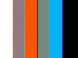
Snapshot of PAL colour bar generator
Introduction
I started this project 3 weeks ago, because I was wondering " is that possible, some AVR MCU to create simple colour bars? " At the beginning, I believed that it's easy. So, I asked some people who knew more about PAL composite video signal.
The first idea was to work with 8.867238 MHz crystal (2 times the color carrier). When I read more about PAL video composite signal creation, I saw that if you want to product colors entire-in-software you must create the color-carrier (4.43 MHz), changing 4 times the phase of color-carrier (one time for each color), to show 4 colours. Except that, you have to change the color-burst from 135 deg to 135+90= 225 deg.
So, the 8.86 MHz is not enough, that`s why I used 17.7 MHz crystal (4 times the color carrier). The easy thing is to create the white and the black bar, the rest of this project, beleave me, it's not easy.
The timing (clock cycles) of any instruction is very important for the phase-shift of the color-carrier and color-burst signals. You should calculate the cycles before add or remove any instruction.
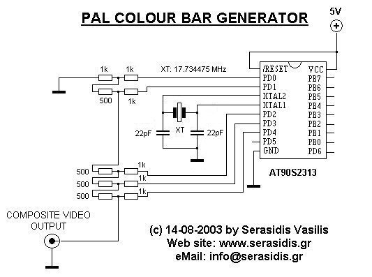
Schematic diagram of colour bar generator
The circuit
The circuit iis constituted by AT90s2313 running at 17.734475 MHz (overclocked) and a , 5-bit DA converter (R2R-ladder) with 10 resistors.
I know, it's not a good idea to overclock 77 % upper than the working frequency of the MCU, but for a few hours, nothing wrong will happen.
Programm (write) the MCU with colour_bar_gen.hex that it's included in colour_bar_gen.zip file, connect it on composite video connector (or scart adapter) of your TV, power-on the circuit and you will see on TV, 6 vertical bars, 4 in color, 1 white and 1 black.
I won't make any explanation about "how does the PAL video signal is working" because I will need a lot of web pages to do that. Maybe some one of you, have the knowledge and the time, to continue this project..
14.08.2003 by Serasidis Vasilis
|
|
The schematic, source code and hex file v1.0. All in colour_bar_gen.zip |
If you improve the source code of this project, please inform me.
Improvements:
01.11.2003 by Zdenek Zechovsky. He improved the original source code, adding new features.
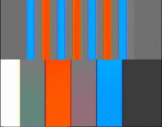
New feautures:
1. vertical synchronization pulses added.
2. odd and even frames
3. picture is cut in two pieces, bottom bars is periodically moving left and right
4. The line 64us period is control by timer 0.
The only change at the hardware is the use of 510 ohm resistors, instead 500 ohm.