![]()
![]()
Introduction
My first attempt with RF modules was with TLP and RLP418 modules. TLP and RLP418 modules work at 418 MHz with slow data-rate (typical 4.8 kbits/sec). The TLP-418 module transmits and the RLP-418 module only receives data. You can't make a bi-directional communication with only one couple of this modules. The solution of this problem is the use of TRW-24G transceiver modules (transceiver = transmitter + receiver). This modules work at 2.4 GHz frequency with GFSK modulation, and the data-rate is 250Kbps and 1Mbps (1 mega bit/second!)
|
TRW-24G Specification
- Frequency Range: 2.4~2.524 GHz ISM band - Modulate Mode: GFSK - Data Rate: 1Mbps; 250Kbps - Multi channel operation: 125 channels, Channel switching time<200uS, Support frequency hopping - Emulated full duplex RF link due to the 1Mbits/s on the air data rate - Simultaneous dual receiver - Data slicer / clock recovery of data - Including decoder, encoder and data buffer and CRC computation - ShockBurst mode for ultra-low power operation and relaxed MCU performance - Sensitivity: -90dBm - Built in antenna - Power supply range: 1.9 to 3.6 V - Low supply current (TX), typical 10.5mA peak@ -5dBm output power - Low supply current (RX), typical18mA peak in receive mode - Supply current in Power Down Mode: 1 uA - Operating Temperature: -40~+85 Centigrade - Size: 20.5*36.5*2.4mm - 100% RF tested - Competitive price |
Applications
- Wireless mouse, keyboard, joystick - Wireless data communication - Alarm and security systems - Home automation - Wireless Earphone - Telemetry - Surveillance - Automotive
|
description
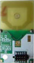
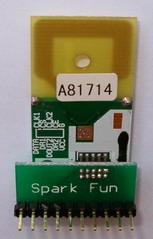
First of all I would like to say that the TRW-24G connector pins is too small (~1mm pin to pin). For that I order the adaptor PCB that is convert the small connector of RF module, to standard pin connector. The pin order of RF modules in schematic diagram is based on pin order of pin adaptor, and not on pin order of the module's connector.
|
>> RF module without pin adaptor |
>> RF module with pin adaptor |
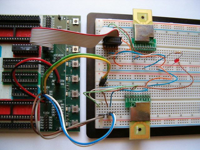
My circuit is constituted by 2x TRW-24G modules, 1x AT90S2313 microcontroller and 1x MAX202 TTL to RS232 voltage level converter. The RF modules work with +3.3V not with +5V. I connected this modules to STK500 development board and I set the VTG voltage to 3.3V from programmer's software in AVRstudio. For serial communication I used the internal MAX202 of STK500 board, that works at +5V power supply. There is no problem with that, but the AT90S2313 MUST work at 3.3V or else you will burn the RF modules if you send +5V instead +3.3V (max. 3.6V).
When you power-on this circuit, the AVR will configure the IC1 as receiver and IC3 as transmitter. Then, the AVR will check the DR1 pin of IC1 for incomming data. If DR1 pin of IC1 is LOW (logic '0') the AVR will send serially from IC3 the 5 byte address of the module that wants to send the data (AA,BB,CC,DD,EE hex address) and the Payload bytes which is the data that wants to send (31,32,33,34 hex, are the same as 1,2,3,4 ASCII). When AVR pushes the CE1 pin of IC3 to LOW ('0') the IC3 transmits the data with baud rate of 250kbps (I set the communication to 250Kbps not to 1Mbps). After some small delay, the AVR reads again the DR1 pin of IC1 for incoming data. In this step the DR1 pin of IC1 goes to logic '1' because receiver's buffer now has the 4 bytes (payload bytes) that we had transmitted before with IC3. The LED1 it will flash for a moment to show that the receiver's buffer has incoming data. Then, the AVR will read these 4 bytes and send them serial via PD1 and MAX202 to PC with baud rate 9600bps/8/n/1. When AVR reads all data from IC1, the LED1 it will be turned-off.
You can connect the CN1 to COM1 serial port of your PC, run the Hyperterminal (start->programs->accesories->communications->hyperterminal) and set it at COM1 with 9600bps/8/N/1. When you power-on this circuit you will see some small flash in the LED1 and after a small delay you can see the ASCII characters <1234> in Hyperterminal's screen.
>> Schematic of the electronic circuit.
The TRW-24G modules are transmitters and receivers both. The function is dependent by the configuration of each module. When you power-on the module, you have to send 2 or 16 serial bytes to configure the modules. The method to configure this RF modules is described in this manual.
Another great tool for Windows, to make the configuration file of 16 bytes, is nRF Configuration Word Generator and is created by Michael Mittermayr.
(c) 12.08.2005 by Serasidis Vasilis