Designed at January 2006 by Vassilis Serasidis.
Published at 27.Jul.2010 by Vassilis Serasidis .
The source code was written in AVR assembly language.
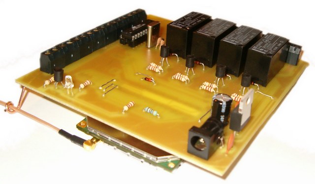
Picture 1: The SMS remote controller V3.0.
Introduction.
It's been passed a lot of years since my first SMS remote control. The reason I stoped developing the source code of my previous circuit was that the T10s was not available in the market sinse a lot of years. So, people could not find very easy that cell phone to build the circuit. Two years later I built another one remote control based on GSM module. I choose the GM-47 sony-ericsson module because it was very easy to handle it via AT commands. Moreover, the price was low enough for experiments. Finaly, I decided to release the source code under GNU General Public Licence V3 If you don't agree with the terms please DO NOT download or use any part of this project (schematic diagram, source code, hex code, PCB, etc).
What is this circuit for?
With this circuit you can power-ON or Power-OFF a lot of electric/electronic devices such as aDSL modem, personal computers, water boilers, water pumps, garage doors, lights and many more. Moreover, you can watch the status of 8 switches. These switches can be connected with reed switches to the windows and the doors of your house. Just like a security system.
The circuit I have made has the following specifications:
|
- 4 relays to Power-ON or OFF any electronic/electric device. - 8 digital inputs for reading normal swiches or reed switches. - Very few and cheap components. - SMS command execution is protected under a programmable password (for avoiding false SMS commands from other persons). |
Picture 2: The schematic diagram of SMS remote control v3.0 (click to enlarge).
The schematic diagram.
This circuit is constituted by an AVR micro-controller (ATtiny2313) at 4MHz, the GM-47 GSM module, a SIM card and 4 relays. The GM-47 module works at 3.3V and is powered by the voltage stabilizer IC1. The micro-controller IC2 can work with power from 2.7V-5.5V when the speed is under 10MHz. So we power it at 3.3V because this is the voltage level that works GM-47 module. The data connection between GM-47 and ATtiny2313 is done at 9600 bps. The voltage level for this communication is 3.3V from AVR's side and 2.7V from GM-47 side. Because of this voltage difference I used the D4 diode to do the voltage level adaptation.
The connection of the SIM card with the GM-47 is been made by the SIM-holder K4 and the presence of the SIM card into the SIM-holder is been made by the switch SW on SIM-holder. The LED D3 when it flashes, indicates that the connection to the cell phone network has been done properly. When the module cannot been connected to any cell phone network, the LED stays always ON (it's not blinking).
The GM-47 has digital and analog inputs-outputs it self but I didn't use them to avoid a malfunction with the danger of destroying the GSM module.
|
Picture 3: the fuses that must be programed the ATtiny2313. |
What the AVR micro-controller does.
After you power-on the circuit the IC2 (ATtiny2313) waits until GM-47 is initialized, by reading the SIM card and connects to the GSM network that SIM card supports. After the connection to the network, the AVR sends the command <AT+CPMS="ME"> to select the GM-47 memory as SMS storage memory. If the answer of the module is not <OK> the AVR sends again the same command. If the answer is <OK> the AVR sends the next command <AT+CMGF=1>. This command says to the module to read the SMS as text and not as PDU format that we used in the past with T10s cell phone. The next command is <AT+CSDH=0> that removes some information from the SMS, like SMS server's phone number and the date and time. This is done to make the SMS smaller to be handled easiest by the AVR. The next command is <AT+CMGR=1> to read the SMS that is stored in the first memory address of the GM-47.
If there is an SMS, the AVR reads it and checks if there is the correct password. Initially the password is 1234 and can be changed by the user. Then, checks if the next character is the "*" (star). This symbol means: "Change the password with the following 4 numbers or letters". Then is searching to find the words <RelayX=Y>. When "X" means the relay number (1-4) and "Y" means 0 or 1 (On or OFF). For example command <Relay2=1> means "Arm the 2nd relay" and <Relay3=0> means "Disarm the 3rd relay". After that the AVR checks again the SMS to see if there is the word <Status> with small , capital or mixed letters written in SMS. If there is, the AVR reads the status of the switches (Open or Closed) and the status of the relays (ON or OFF) and sends back an SMS to the person who sent the initial SMS. Obviously, your SIM card must have credits to send SMS!
At the end the AVR deletes the SMS from the GM-47 first storage address and starts over sending again the AT commands .
|
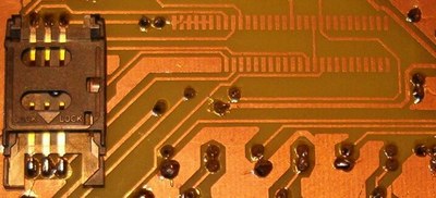
Picture 4: The PCB without the GM-47 connector. |
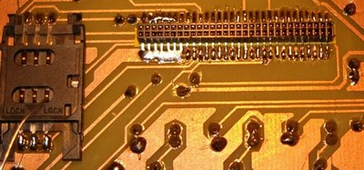
Picture 5: The PCB with the GM-47 connector soldered. |
Sending an SMS to the remote control
Before you start using this circuit make sure you have disabled the PIN code of the SIM card
You can send an SMS from any cell phone to the remote control by following one of the above command syntax:
|
A) 1234*5678 Relay1=1 Relay2=0 Relay3=1 Relay4=1 Status B) 1234 Relay1=1 Relay2=0 Relay3=1 Relay4=1 Status
C)
D) 1234 Status E) 1234 Relay2=0 |
In case A we have the maximum of selections. We send the initial password 1234 and we change it to 5678. We arm the relay-1, relay-3, relay-4 and disarm the relay-2. Moreover, by writing the word <Status> we ask for the status of the 8 swiches and the status of the 4 relays.
In case B we arm the relay-1, relay-3, relay-4, disarm the relay 2 and ask for the status of the relays and the switches.
In case C we do the same bypassing the words <Relay>. We write the number of the relay we want to change and the status we want to have for this relay. for example case C says: armed the relays 1,3,4 and disarmed the relay 2. Moreover, we ask for the status.
In case D we ask only for the status of relays and switches.
In case E we change the status of only one relay. In this case relay-2 will be disarmed.
|
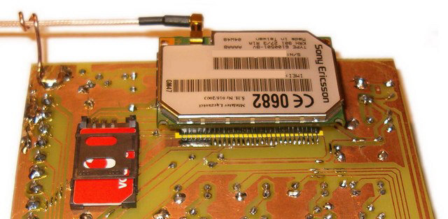
Piucture 6: The placement of the GM-47 module on the PCB. See the yellow thin film I put under the connector. This film is been put to protect the circuit from short-circuit between copper strip and the connector. |
|
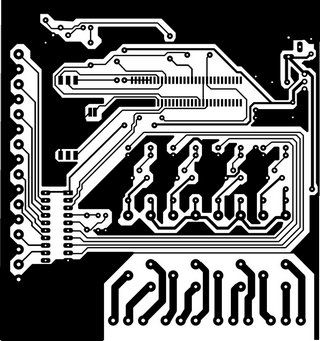
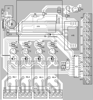
Picture 7: The PCB of this project. |
|
Picture 8: The placement of the components on PCB. |
![]() Download schematic, source code (in AVR assembly language), PCB.
Download schematic, source code (in AVR assembly language), PCB.
Designed and published by Vassilis Serasidis at 27.Jul.2010
